This site uses cookies and related technologies, as described in our privacy policy, for purposes that may include site operation, analytics, enhanced user experience, or advertising. You may choose to consent to our use of these technologies, or manage your own preferences.
4-way ceiling diffusers with fixed core
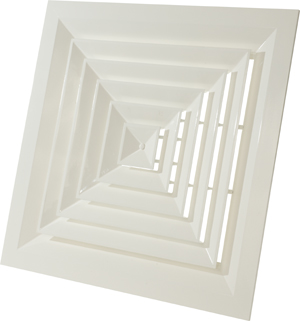
 and central screw mounting.
Brand
Cairox
Application
For air supply and exhaust in ventilation and air conditioning systems
Material
Aluminium
Colour
Standard colour white, RAL 9016
Composition
Frame and fixed inner core made of aluminium
Fixed 4-way directional blades
Mounting
Fixing by central screw in the crossbar of the plenum box.
Accessories
Opposite blade volume control damper type DSF
Plenum box with side duct connection type REF
Insulated plenum box with side duct connection type REFISO
Plenum box regulating valve CRC
Text for tender
The air supply ceiling diffusers are square with a fixed 4-way pattern with a fixed core. They are made of aluminium and steel in white powder coating RAL 9016 and are supplied with a volume control damperand a plenum box with a crossbar.
Cairox type APW-4+DSF+REF
The air supply ceiling diffusers are square with a fixed 4-way pattern with a fixed core. They are made of aluminium and steel in white powder coating RAL 9016 and are supplied with a volume control damperand a plenum box with a crossbar.
Cairox type APW-4+DSF+REF
Order example
APW-4, 444 + REF + DSF
Explanation
APW-4 = Diffuser type
444 = Diffuser size
Accessories (Optional)
REF = Plenum box
DSF = Volume control damper
Artikelen
Article selection assistant
Type
Article number
Type
E-shop
I100117225011
CHR 225 PRO L
I100117225211
CHR 225 PRO R
I100117325011
CHR 325 PRO L
I100117325211
CHR 325 PRO R
I100117400011
CHR 400 PRO L
I100117400211
CHR 400 PRO R
I100117600011
CHR 600 PRO L
I100117600211
CHR 600 PRO R
=> Stock product central warehouse, except sales
=> Article with a volume discount
Minimum order quantity: 2 pieces
Dimensions
L x H [mm]
APW-4 294/150
145 x 145
APW-4 369/225
220 x 220
APW-4 444/300
295 x 295
APW-4 519/375
370 x 370
APW-4 595/445
445 x 445
Quick selection
APW-4
294/150
369/225
444/300
519/375
595/450
LxH
145x145
220x220
295x295
370x370
445x445
Q
Ak
0.0109
0.0244
0.0435
0.0679
0.0978
B
1.2
2.4
3.6
1.2
2.4
3.6
1.2
2.4
3.6
1.2
2.4
3.6
1.2
2.4
3.6
100
H=
2.7
0.52
0.17
0.1
Vz
H=
3.2
0.2
0.11
0.08
H=
3.8
0.11
0.08
0.06
Vk
2.5
X0,25
1.8
Ps
4
Lw(A)
22
150
H=
2.7
0.78
0.26
0.16
0.52
0.17
0.1
Vz
H=
3.2
0.29
0.17
0.12
0.2
0.11
0.08
H=
3.8
0.17
0.12
0.09
0.11
0.08
0.06
Vk
3.8
1.7
X0,25
2.1
1.8
Ps
10
2
Lw(A)
32
<20
200
H=
2.7
1.04
0.35
0.21
0.7
0.23
0.14
Vz
H=
3.2
0.39
0.22
0.16
0.26
0.15
0.1
H=
3.8
0.22
0.16
0.12
0.15
0.1
0.08
Vk
5.1
2.3
X0,25
2.4
2
Ps
18
4
Lw(A)
39
22
300
H=
2.7
1.04
0.35
0.21
0.78
0.26
0.16
Vz
H=
3.2
0.39
0.22
0.16
0.29
0.17
0.12
H=
3.8
0.22
0.16
0.12
0.17
0.12
0.09
Vk
3.4
1.9
X0,25
2.5
2.1
Ps
8
3
Lw(A)
32
20
400
H=
2.7
1.39
0.46
0.28
1.04
0.35
0.21
0.83
0.28
0.17
Vz
H=
3.2
0.52
0.3
0.21
0.39
0.22
0.16
0.31
0.18
0.13
H=
3.8
0.3
0.21
0.16
0.22
0.16
0.12
0.18
0.13
0.1
Vk
4.6
2.6
1.6
X0,25
2.9
2.5
2.2
Ps
15
5
2
Lw(A)
39
28
<20
600
H=
2.7
1.56
0.52
0.31
1.25
0.42
0.25
1.04
0.35
0.21
Vz
H=
3.2
0.59
0.34
0.23
0.47
0.27
0.19
0.39
0.22
0.16
H=
3.8
0.34
0.23
0.18
0.27
0.19
0.14
0.22
0.16
0.12
Vk
3.8
2.5
1.7
X0,25
3.1
2.7
2.5
Ps
10
4
2
Lw(A)
38
29
21
800
H=
2.7
2.09
0.7
0.42
1.67
0.56
0.33
1.39
0.46
0.28
Vz
H=
3.2
0.78
0.45
0.31
0.63
0.36
0.25
0.52
0.3
0.21
H=
3.8
0.45
0.31
0.24
0.36
0.25
0.19
0.3
0.21
0.16
Vk
5.1
3.3
2.3
X0,25
3.7
3.2
2.9
Ps
18
8
4
Lw(A)
45
36
28
1000
H=
2.7
2.09
0.7
0.42
1.74
0.58
0.35
Vz
H=
3.2
0.78
0.45
0.31
0.65
0.37
0.26
H=
3.8
0.45
0.31
0.24
0.37
0.26
0.2
Vk
4.1
2.8
X0,25
3.7
3.3
Ps
12
5
Lw(A)
41
34
1200
H=
2.7
2.5
0.83
0.5
2.09
0.7
0.42
Vz
H=
3.2
0.94
0.54
0.38
0.78
0.45
0.31
H=
3.8
0.54
0.38
0.29
0.45
0.31
0.24
Vk
4.9
3.4
X0,25
4.2
3.7
Ps
17
8
Lw(A)
46
38
Symbols and specifications
Q = Air volume in m³/h
Ak = Effective surface (free area) in m²
B = Distance between the diffusers in m
H = Installation height of the diffusers in m
Vz = Maximum velocity at the occupied zone according to distance between the diffusers and installation height in m/s
Vk = Average effective velocity through the diffuser in m/s
X0.25 = Throw length in m at an end velocity Vt of 0,25m/s
µPs = Static pressure loss given in P
Lw(A) = Acoustic power in dB(A)
The throw X0.25 is given at an end velocity of 0.25m/s for a smooth ceiling without any obstacles.
The values are given for isothermal supply air. Throw distances for cooling conditions at -11K can be calculated by dividing the X0.25 values with factor 1.1. For heating purposes at Dt of +11K a multiplier of 1.1 should be applied to the given X0.25 value.
In order to achieve a high comfort level, selections can be made according to the maximal velocity at the occupied zone Vz. These values are given at distances between diffusers B and installation heights H. Velocities Vz lower than, or equal to 0,25m/s at the occupied zone are advised.
The pressure losses Ps are given for diffusers without damper of with fully opened damper.
The acoustic power values Lw(A) are given for diffusers without damper of with fully opened damper without room attenuation. Acoustic powers below 20dB(A) are mentioned as "<20" in the tables.
For all special requirements, please contact our engineering office.