PRODUCTS


EShop-number
Password
Welcome to CAIROX BELGIUM
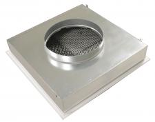
PS/PPTMB (RAL9016) • Perforated diffusers for system ceilings
 |
 |


- Perforated diffusers
- Square
- Steel
- White, RAL 9016
- 1-4 way supply pattern
Air supply diffusers with adjustable 1- to 4-way pattern perforated plate for mounting in 600 x 600 mm system ceilings.
Brand
- Cairox
Application
- For air supply in ventilation and air conditioning systems
Material
- Frame: aluminium
- Inner part: steel
Colour
- Standard colour white, RAL 9016
- Other colours available upon request
Composition
- Perforated front plate in white finish RAL 9016 with incorporated plenum box
- Perforated inner part to be opened easily by push-push system
Text for tender
- The square air supply system ceiling diffusers are of the multidirectional type with a perforated front plate and an incorporated plenum box. They are made of aluminium and steel with white powdercoating finish RAL 9016.
- Cairox type PS/PPTMB
Order example
- PS/PPTMB, 200
Explanation
PS/PPTMB = Diffuser type
200 = Diffuser size (connection diameter)


Requesting information. Please wait a moment...