PRODUCTEN


EShop-nummer
Wachtwoord
Welcome to CAIROX BELGIUM
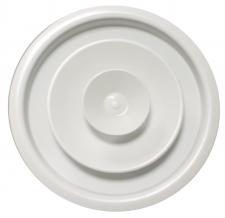
SRR-D (RAL9016) • Round ceiling diffusers
 |
 |

- Circular conical diffusers
- Circular
- Aluminium
- White, RAL 9016
- Adjustable cones and damper
Accessoires
SRR-DMC • Mounting clips for SRR-DRound ceiling diffusers with adjustable cones
Brand
- Cairox
Application
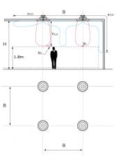
- For supply and exhaust air in ventilation and air conditioning systems
Material
- Aluminium
- Inner cone made of ABS
Colour
- White, RAL 9016
- Other colours available upon request
Composition
- Adjustable rings
- Adjustable damper in plastic
Mounting
- Direct mounting by the collar in the duct
Accessories
- Clips mounting system SRR-DMC for plasterboard ceiling
Text for tender
- The circular ceiling diffusers shall have adjustable diffusion rings. They shall be made of aluminium with white powder coated finish RAL 9016 and supplied with volume control damper
- Cairox type SRR-D
Order example
- SRR-D, 200
Explanation
SRR-D = Type diffuser
200 = Size diffuser (Ø diffuser neck connection)

Informatie aanvragen. Even geduld a.u.b...