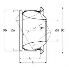
JET nozzles are used for hot or cold air supply in ventilation and air conditioning systems where a long throw, high induction and low sound levels are required.
The nozzles are manually adjustable to be set for cooling or heating purposes
Material
Aluminium
Colour
Standard colour grey (alu-look), RAL 9006
Composition
The nozzle can be adjusted manually to direct the air flow over 30° in all directions.
Mounting
Wall or rectangular duct mounting
Cover flange to conseal mounting screws, removable by quarter turn.
Mounting on the side of round ducts by means of a pipe branch and connection type ARG and MDV, or directly into the round duct
Text for tender
The air supply diffusers are of the JET type for long throw application. They are made aluminium finished grey RAL 9006.
ATC Type JET-GDA
The air supply diffusers are of the JET type for long throw application. They are made aluminium finished grey RAL 9006.
ATC Type JET-GDA
Order example
JET-GDA, 315
Explanation
JET-GDA = Diffuser type
315 = Connection diameter
Dimensions
JET-GD
ØD [mm]
ØA [mm]
ØB [mm]
ØC [mm]
L1 [mm]
L2 [mm]
125
125
123
61
170
70
100
150
150
148
75
200
85
113
160
160
158
80
200
85
115
200
200
197
105
266
109
143
250
250
248
128
315
135
180
315
315
313
165
395
173
230
400
400
398
210
495
217
285
Quick selection
JET-GD(A)
125/60
150/75
160/80
200/105
250/128
315/165
400/210
Q
Ak
0.0028
0.0044
0.005
0.0087
0.0129
0.0214
0.0346
75
Vk
7.4
4.7
4.2
X0,25
16.3
14.5
14.1
Ps
35
14
11
Lw(A)
<20
<20
<20
100
Vk
9.9
6.3
5.6
3.2
X0,25
19
17.4
16.9
13.7
Ps
62
25
20
7
Lw(A)
<20
<20
<20
<20
150
Vk
9.5
8.3
4.8
3.2
X0,25
21.4
20.7
17.5
14.9
Ps
57
44
15
7
Lw(A)
21
<20
<20
<20
200
Vk
12.6
11.1
6.4
4.3
X0,25
24.1
23.5
20.3
17.6
Ps
100
78
26
12
Lw(A)
28
26
<20
<20
300
Vk
9.6
6.5
3.9
X0,25
24.1
21.4
18.2
Ps
58
27
10
Lw(A)
26
<20
<20
400
Vk
12.8
8.6
5.2
3.2
X0,25
26.8
23.9
20.7
19
Ps
103
47
17
7
Lw(A)
33
25
<20
<20
500
Vk
10.8
6.5
4
X0,25
26
22.6
21
Ps
74
27
10
Lw(A)
31
<20
<20
600
Vk
12.9
7.8
4.8
X0,25
27.6
24.2
22.6
Ps
105
39
15
Lw(A)
35
20
<20
700
Vk
9.1
5.6
X0,25
25.6
24
Ps
53
20
Lw(A)
24
<20
800
Vk
10.4
6.4
X0,25
26.8
25.2
Ps
68
26
Lw(A)
28
<20
1000
Vk
13
8
X0,25
28.7
27.2
Ps
107
41
Lw(A)
34
23
1200
Vk
9.6
X0,25
28.9
Ps
58
Lw(A)
29
1400
Vk
11.2
X0,25
30.3
Ps
79
Lw(A)
33
1500
Vk
12
X0,25
30.9
Ps
91
Lw(A)
36
Symbols and specifications
Q = Air volume in m³/h
Ak = Effective surface (free area) in m²
Vk = Average effective velocity through the grill in m/s
X0.25 = Horizontal throw in m at an endvelocity Vt of 0.25 m/s
Ps = Static pressure loss given in Pa
Lw(A) = Acoustic power in dB(A)
The throw X0.25 is given without deflection of the airstream at an end velocity of 0.25m/s. The distances are given without coanda effect.
The values are given for isothermal supply air. Throw distances for cooling conditions at -11K can be calculated by deviding the X0.25 values with factor 1.1. For heating purposes at Dt of +11K a multiplier of 1.1 should be applied to the given X0.25 value.
The acoustic power Lw(A) are given for grilles without room attenuation. Acoustic powers below 20dB(A) are mentioned as "<20" in the tables.
For special requirements, please contact our engineering office.