PRODUCTS
EShop-number
Password
Welcome to CAIROX BELGIUM
P-DVS (RAL9005) • Steel supply valves


- Air valves
- Steel
- Black, RAL 9005
- For air supply
- Pulsion
Accessories
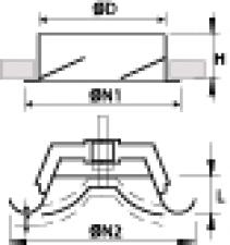
TR • Clamping rings for valve mounting framesSteel air supply valves with adjustable core and 50 mm mounting frame
Brand
- Cairox
Application
- Wall or ceiling mounted valves used for air supply inside buildings.
Material
- Steel
Colour
- Black, RAL 9005
Composition
- Pressed steel grille with adjustable core supplied with galvanized steel mounting frame
Mounting
- Fixing in the mounting frame
Accessories
- Mounting ring TR for clamping the mounting frame on tile ceiling plates
Order example
- P-DVS, 100
Explanation
P-DVS = Type valve (incl. mountingframe and clamping ring)
100 = Connection diameter
Text for tender
- The air supply valves shall be of the high pressure loss type with adjustable core and made of steel. They shall be supplied with mounting frame
- White finish RAL 9005
- Cairox type P-DVS (RAL 9005)
Requesting information. Please wait a moment...


