PRODUCTEN
EShop-nummer
Wachtwoord
Welcome to CAIROX BELGIUM

P-DVS (RAL9005) • Steel supply valves

  • Air valves
  • Steel
  • Black, RAL 9005
  • For air supply
  • Pulsion

Steel air supply valves with adjustable core and 50 mm mounting frame

Brand

  • Cairox

Application

  • Wall or ceiling mounted valves used for air supply inside buildings.

Material

  • Steel

Colour

  • Black, RAL 9005

Composition

  • Pressed steel grille with adjustable core supplied with galvanized steel mounting frame

Mounting

  • Fixing in the mounting frame

Accessories

  • Mounting ring TR for clamping the mounting frame on tile ceiling plates

Order example

  • P-DVS, 100

Explanation

P-DVS = Type valve (incl. mountingframe and clamping ring)

100 = Connection diameter

Text for tender

Kopiëren
  • The air supply valves shall be of the high pressure loss type with adjustable core and made of steel. They shall be supplied with mounting frame
  • White finish RAL 9005
  • Cairox type P-DVS (RAL 9005)

Artikelen

Artikelselectie-assistent
Type
Lengte [mm]
Spleten
Aansluitmaat
Artikelnummer Type Lengte [mm] Spleten Aansluitmaat E-shop
A04650T120625 GYP-P-LINE - 1 - L= 625 MM - A 625 1 A
A04650T120A00 GYP-P-LINE - 1 - L=1000 MM - A 1000 1 A
A04650T120C50 GYP-P-LINE - 1 - L=1250 MM - A 1250 1 A
A04650T220625 GYP-P-LINE - 2 - L= 625 MM - B 625 2 B
A04650T220A00 GYP-P-LINE - 2 - L=1000 MM - B 1000 2 B
A04650T220C50 GYP-P-LINE - 2 - L=1250 MM - B 1250 2 B
A04650T320625 GYP-P-LINE - 3 - L= 625 MM - C 625 3 C
A04650T320A00 GYP-P-LINE - 3 - L=1000 MM - C 1000 3 C
A04650T320C50 GYP-P-LINE - 3 - L=1250 MM - C 1250 3 C
=> Voorraadproduct centraal magazijn behoudens verkoop

Quick selection

QØ100125
r-3010-7015
15X0.2<0,5     
Ps50     
Lw(A)28     
25X0.2 0.6 0.5  
Ps 26 17  
Lw(A) 25 <20  
50X0.2  1.11.60.9 
Ps  136818 
Lw(A)  <2033<20 
100X0.2  2.1 2.61.6
Ps  51 7513
Lw(A)  37 36<20
200X0.2     3.3
Ps     50
Lw(A)     38

Symbols and specifications

  • Q = Air volume in m³/h
  • X0.2 = Horizonatal throw distance with an endvelocity vt of 0.2m/s given in m
  • Ps = Static pressure loss in Pa
  • Lw(A) = Acoustic power in dB(A), based upon measured Lp acoustic pressures increased by 4 dB(A) room attenuation
  • r = Gap between the central core and the valve body

Selection Graph

Symbols

  • Q = Air volume in l/s and m³/h
  • Pt = Total pressure loss in Pa
  • X0.2 = Horizontal throw at end velocity of 0.20 m/s in m
  • Lw(A) = Acoustic power in dB(A)
  • r = Gap between the central core and the valve body in mm

Placement instruction

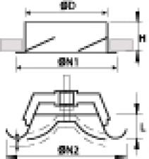
Dimensions

ØD [mm]

ØN1 [mm]

h [mm]

ØN2 [mm]

L [mm]

P-DVS 100

99

125

45

137

28

P-DVS 125

124

150

45

164

29

HELPCopyrightSales conditionsCookie policyfujitsu-airco.be

Informatie aanvragen. Even geduld a.u.b...