PRODUCTS
EShop-number
Password
Welcome to CAIROX BELGIUM
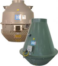
HF D • Anti-acid roof fans


- Roof fans
- AC motor
- up to 6.000 m³/h
Anti-acid roof fans with built-in AC motor outside of the air flow
Brand
- Hürner Luft- und Umwelttechnik
Application
- The HF D roof fans are ideally suitable for exhaust of aggressive gasses
- They are particularly applicable for the extraction in:
- Laboratia
- Chemical and petrochemical industry
- Metal treatment industry
- Food and beverage industry
- Water treatment systems
Composition
- The fan housing is made of fire-resistant polyethylene (PEs/PE-FR) and is composed by 2 parts bolted together
- The housing is fitted with a splinter guard
- The impeller is made of fire-resistant polypropylene (PPs/PE-FR) and is of the backward-curved blade type, statically and dynamically balanced according to Q 6.3 (VDI 2056)
- Motor out of the airflow (fully encapsulated)
- Squirrel cage asychronous type B5
- Protection: IP55
- Insulation class F
- Supply: 400Vac 3ph 50hz
Accessories
- Roof sockets
- Roof socket for brickwork base for HF D, type DOHF
- Roof socket with base for HF D, type DOSHF (price on request)
- Roof socket with sound-insulating base for HF D, type DOGSHF (price on request)
- Frequency inverter 3x400V, type FIS(-C)-44-B
- Flexible PVC sleeve, type PVC (mounting only possible on roof curb DOHF, DOSHF, DOGSHF)
Options
- 2-speed motors
- ATEX version follow ATEX 94/9/CE
- 230Vac on demand (plug&play - not suited for transformer and frequency regulation)
- Horizontal mounting available upon request (technical drawing can be downloaded in the downloads section)
Other available products
These HF D fans are just a few of the very wide range of HF-fans. For a selection and price, perfectly tailored to your project, please send your request to engineering@cairox.be.
Order example
HF D 160-17D 400V 1450 rpm
- HF D = type of fan
- 160 = diameter
- 17 = impeller type
- D = direct driven
- 400V = supply
- 1450 rpm = speed
Requesting information. Please wait a moment...


