PRODUCTS
EShop-number
Password
Welcome to CAIROX BELGIUM
HF R EC • Anti-acid centrifugal fans with EC motor


- Centrifugal fans
- EC motor
- up to 4.000 m³/h
Accessories
PVC • Flexible connectors AVM • Anti-vibration mounts DMD-C • Differential pressure transmitters with built-in controller KC (EC) • Motor protection covers ESCP • Potentiometers 0-10V
Datasheet
Manual / Operation manual HF R Centrifugal fans
Wiring / Diagram / Safety switch HF R Centrifugal fans
Wiring / Diagram / 0.37kW EBM Papst (discontinued)
Wiring / Diagram / 1.1kW EBM Papst (discontinued)
Wiring / Diagram / WEG-motor
Wiring / Diagram / ADDA motor
Certificates / CE
Other / Chemical resistance table
Anti-acid centrifugal fans with EC motor
Brand
- Hürner Luft- und Umwelttechnik
Application
- The fans are suitable for extraction of aggressive gasses
- They are particularly applicable for the extraction in:
- Laboratia
- Chemical and petrochemical industry
- Metal treatment industry
- Food and beverage industry
- Water treatment systems
Composition
- The casing is made of fire resistant polyethylene (PEs/PE-FR,RAL7036)
- The housing is fitted with a splinter guard and condensate drain at its deepest point
- The impeller is made of fire-resistant polypropylene (PPs/PP-FR) and is of the backward-curved blade type, statically and dynamically balanced according to Q 6.3 (VDI 2056)
- The impeller can be demounted without removing the housing
- Supply: 230Vac 1ph
- Protection: IP55
- Insulation class: F
- Integrated potentiometer for regulation of the motor
- Integrated safety switch
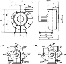
- Standard orientations: GR360, GL360, GR090 and GL090 - other orientations available on request
Accessories
- Flexible connections made of PVC, type PVC
- Set anti-vibration mounth, type AVM
- Protective cover for engine, type KC EC
- Potentiometers 0-10V, type ESCP010
- differential pressure regulators DMD-C
Options
- ATEX version in accordance with directive ATEX 94/9/CE
- Standard ATEX 3/-G (ATEX zone 2 inside / no ATEX zone outside)
- Terminal box for 0-10V control, price on request
Other available products
These HF R EC fans are just a few of the very wide range of HF-fans. For a selection and price, perfectly tailored to your project, please send your request to engineering@cairox.be.
Order example
- HF R EC 160-17D GR090
HF R: type of fan
EC: EC motor
160: diametre
17: type of impeller
D: direct driven
GR090: casing orientation
Requesting information. Please wait a moment...


