PRODUCTEN


EShop-nummer
Wachtwoord
Welcome to CAIROX BELGIUM
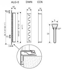
ALG-0 • Aluminium linear wall grilles


- Wall grilles
- Aluminium
- Anodized natural finish
- Fixed blades 0°
Anodized aluminium grilles with fixed blades and a blade pitch of 12.5 mm, deflection 0°
Brand
- Cairox
Application
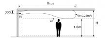
- Used for air supply and air exhaust in ventilation and air conditioning systems
Material
- Aluminium
Colour
- Anodized natural finish
- Other colours available upon request
Composition
- Deflection: fixed 0°
- Single row of horizontal blades
Mounting
- Invisible mounting with clips in mounting frame, type CCN
Accessories
- Mounting frame for clip fixing, type CCN
- Volume control damper, type DWN
- Plenum box, type REW
- Insulating plenum box, type REW ISO
Other available products
- ALG-15 with 15° deflection
Text for tender
- The air supply wall grilles have fixed blades with a clip fixing system and are supplied with a galvanised steel volume control damper.
- Anodized natural aluminium
- Cairox Type ALG-0+CCN+DWN+REW(ISO)
Order example
- ALG-0, 800, 200 + CCN + DWN + REW
Explanation
ALG-0 = Grille type
800 = Length
200 = Height
Accessories (optional)
CCN = Mounting frame
DWN = Volume control damper
REW = Plenum box
Informatie aanvragen. Even geduld a.u.b...