This site uses cookies and related technologies, as described in our privacy policy, for purposes that may include site operation, analytics, enhanced user experience, or advertising. You may choose to consent to our use of these technologies, or manage your own preferences.
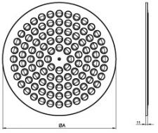
Multinozzle ceiling diffusers with high induction rate, consisting of a circular plate with individual adjustable nozzles arranged in a circular pattern to be equipped with galvanized steel plenum box.
Brand
Cairox
Application
For air supply and exhaust in ventilation and air conditioning systems.
Material
Steel and plastic composite combination
Colour
Standard colour white, RAL 9016
Nozzles and diffuser available in RAL 9016 / 9010 / 9006 / 9005
Composition
Frontplate made of powder coated steel
Nozzles made out op plastic composite
Central screw mounting
Mounting
Fixing by central screw in the crossbar of the plenum box.
Accessories
Circular plenum box RER-B
Circular insulated plenum box RER-BISO
Regulating valve for plenum box type CRC
Text for tender
The air supply ceiling diffusers are circular with a circular arranged nozzlepattern. They are made of a steel powdercoated frontplate in white finish RAL 9016 and nozzles in plastic composite materials. The diffusers are standard delivered with galvanized steel plenumbox equipped with perforated plate and damper in the side entry spigot. The diffuser is centrally screw mounted.
Cairox type CNC-1A + RER-A
The air supply ceiling diffusers are circular with a circular arranged nozzlepattern. They are made of a steel powdercoated frontplate in white finish RAL 9016 and nozzles in plastic composite materials. The diffusers are standard delivered with galvanized steel plenumbox equipped with perforated plate and damper in the side entry spigot. The diffuser is centrally screw mounted.
* niet meer verkrijgbaar / n'est plus disponible / no longer available
Quick selection
CNC 1A - #Nozzles
300 - #22
400 - #42
500 - #68
600 - #100 / 625* - #100
Q
Ak
0.0057
0.0114
0.0153
0.0258
B
1.2
2.4
3.6
1.2
2.4
3.6
1.2
2.4
3.6
1.2
2.4
3.6
50
H=
2.7
0.3
0.12
0.06
0.25
0.1
0.05
Vz
H=
3.2
0.14
0.07
0.04
0.12
0.06
0.03
H=
3.8
0.07
0.04
0.02
0.06
0.03
0.02
Vk
2.4
1.2
X0,25
1.6
1.5
Ps
6
2
Lw(A)
24
<20
75
H=
2.7
0.42
0.19
0.11
0.34
0.15
0.08
0.32
0.14
0.08
Vz
H=
3.2
0.22
0.12
0.07
0.17
0.09
0.06
0.16
0.08
0.05
H=
3.8
0.12
0.07
0.05
0.09
0.06
0.04
0.08
0.05
0.03
Vk
3.7
1.8
1.4
X0,25
1.8
1.7
1.6
Ps
13
4
2
Lw(A)
33
<20
<20
100
H=
2.7
0.53
0.27
0.16
0.42
0.2
0.12
0.38
0.18
0.1
0.3
0.13
0.07
Vz
H=
3.2
0.29
0.17
0.11
0.22
0.13
0.08
0.2
0.11
0.07
0.15
0.08
0.05
H=
3.8
0.17
0.11
0.08
0.13
0.08
0.05
0.11
0.07
0.05
0.08
0.05
0.03
Vk
4.9
2.4
1.8
1.1
X0,25
2.1
1.9
1.8
1.6
Ps
24
7
4
2
Lw(A)
38
23
<20
<20
150
H=
2.7
0.58
0.3
0.19
0.51
0.26
0.16
0.39
0.18
0.11
Vz
H=
3.2
0.33
0.2
0.14
0.29
0.17
0.11
0.21
0.12
0.07
H=
3.8
0.2
0.14
0.1
0.17
0.11
0.08
0.12
0.07
0.05
Vk
3.7
2.7
1.6
X0,25
2.3
2.1
1.8
Ps
16
9
3
Lw(A)
33
27
<20
200
H=
2.7
0.71
0.4
0.26
0.63
0.34
0.22
0.49
0.25
0.15
Vz
H=
3.2
0.43
0.28
0.19
0.37
0.23
0.16
0.27
0.16
0.11
H=
3.8
0.28
0.19
0.14
0.23
0.16
0.12
0.16
0.11
0.08
Vk
4.9
3.6
2.2
X0,25
2.7
2.4
2
Ps
28
16
6
Lw(A)
40
34
23
250
H=
2.7
0.74
0.42
0.28
0.57
0.3
0.19
Vz
H=
3.2
0.46
0.3
0.21
0.33
0.2
0.14
H=
3.8
0.3
0.21
0.16
0.2
0.14
0.1
Vk
4.5
2.7
X0,25
2.8
2.3
Ps
25
9
Lw(A)
40
28
300
H=
2.7
0.85
0.5
0.34
0.64
0.35
0.23
Vz
H=
3.2
0.54
0.36
0.26
0.39
0.24
0.17
H=
3.8
0.36
0.26
0.2
0.24
0.17
0.12
Vk
5.4
3.2
X0,25
3.2
2.5
Ps
35
13
Lw(A)
45
33
350
H=
2.7
0.73
0.42
0.27
Vz
H=
3.2
0.45
0.29
0.21
H=
3.8
0.29
0.21
0.16
Vk
3.8
X0,25
2.8
Ps
18
Lw(A)
37
400
H=
2.7
0.79
0.47
0.31
Vz
H=
3.2
0.51
0.33
0.24
H=
3.8
0.33
0.24
0.18
Vk
4.3
X0,25
3
Ps
23
Lw(A)
41
450
H=
2.7
0.86
0.52
0.36
Vz
H=
3.2
0.56
0.38
0.28
H=
3.8
0.38
0.28
0.21
Vk
4.8
X0,25
3.3
Ps
29
Lw(A)
44
Symbols and specifications
Q = Air volume in m³/h
Ak = Effective surface (free area) in m²
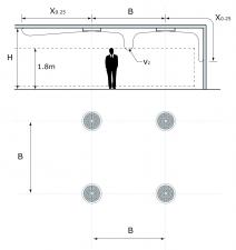
B = Distance between the diffusers in m
H = Installation height of the diffusers in m
Vz = Maximum velocity at the occupied zone according to distance between the diffusers and installation height in m/s
Vk = Average effective velocity through the diffuser in m/s
X0.25 = Throw length in m at an end velocity Vt of 0,25m/s
Ps = Static pressure loss given in Pa
Lw(A) = Acoustic power in dB(A)
The throw X0.25 is given at an end velocity of 0.25m/s for a smooth ceiling without any obstacles.
The values are given for isothermal supply air. Throw distances for cooling conditions at -11K can be calculated by dividing the X0.25 values with factor 1.1. For heating purposes at Dt of +11K a multiplier of 1.1 should be applied to the given X0.25 value.
In order to achieve a high comfort level, selections can be made according to the maximal velocity at the occupied zone Vz. These values are given at distances between diffusers B and installation heights H. Velocities Vz lower than, or equal to 0,25m/s at the occupied zone are advised.
The pressure losses Ps are given for diffusers without damper of with fully opened damper.
The acoustic power values Lw(A) are given for diffusers without damper of with fully opened damper without room attenuation. Acoustic powers below 20dB(A) are mentioned as "<20" in the tables.
For all special requirements, please contact our engineering office.