PRODUCTEN
EShop-nummer
Wachtwoord
Welcome to CAIROX BELGIUM
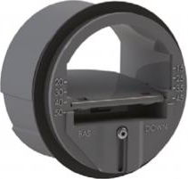
KVR-R • Adjustable constant air volume dampers


- Circular
- Flame retardant PVC
- Standard
- 50-250 Pa
Accessoires
SD TX • Screwdriver TORXAlternatieve producten
KVR-R HP • Adjustable constant air volume dampersConstant volume control dampers made of fire retardant plastics. The range covers an air flow range between 15 up to 700 m³/h within a pressure range from 50 up to 250 Pa. Air flow can easily be adjusted within the airflow range of each damper.
Application
- To obtain constant air volumes in ventilation and air conditioning systems within a pressure range between 50 and 250Pa
- For air supply or exhaust duct systems
- Maximum working temperature 60°C
Colour
- Black
Composition
- Valve and piston made out of fire retardant plastics M1
- Body in fire retardant plastics M1
- Stainless steel calibrated spring
- Rubber air-tight sealing
Mounting
- For mounting inside round ducts
- Horizontal as well as vertical mounting applicable
- For horizontal mounting, the BAS marking has to be at the bottom
- To be installed in accordance with the correct air flow direction
- To be installed in the air intake at a minimum distance of three times the diameter of the duct starting from the air intake grilles and at the same distance from places with a high degree of turbulence in the duct, such as branches, bends,….
- To be installed in the air outtake at a minimum distance of one time the diameter of the duct starting from the extraction grilles and at the same distance from places with a high degree of turbulence in the duct, such as branches, bends,….
- The volume control damper has to be easily accessible for maintenance
Accessories
- Screw driver Torx T10 for unscrewing the screw for adjusting the air flow rate of the
regulator.
Other available products
- KVR-R-HP: High pressure constant volume dampers with a
pressure range between 150 and 600Pa
Informatie aanvragen. Even geduld a.u.b...


