PRODUCTS
EShop-number
Password
Welcome to CAIROX BELGIUM
CR2+CFTH • Circular fire dampers EI120S
 |
 |

- Fire dampers
- Circular
- EI120S
- With fuse 72°C
- EN1366-2
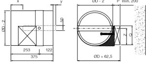
- Ø 355 - 630
Accessories
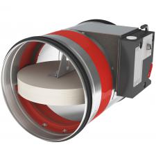
FDC CFTH • Begin/end of range switch for CFTHCircular fire dampers with a fire resistance of 120 minutes. When the temperature in the damper rises above 72 °C the fusible link will break and the damper will close. When closed, the expanding material around the fireblade will swell and assure a fire and air-tight seal against hot air and smoke. The tunnel is made out of galvanized steel. The CR2 + CFTH fire dampers have a manual operating mechanism with indication of the blade position. Optionally, an end or begin of range switch FDC CFTH can be added to the mechanism. The operating mechanism can be removed easily, for inspection purposes or for replacing the fusible link.
Application
- Fire compartimentation
- To close and seal off ventilation ducts in case of fire
- For air temperatures of -10°C up to temperature of fusible link
- For air with RV 0-96%
- Range of Ø355 up to Ø630 mm
- For size Ø100 upto Ø315 see type CR120 + MFUS
- To be mounted horizontally or vertically
Material
- Galvanized steel
Construction
Composition
- Galvanized steel tunnel
- Fireproof blade in fibersilicate
- Intumescent strip around the valve
- Manual control mechanism CFTH with fusible link 72 °C
- 1. Refractory casing (made out of galvanised steel)
- 2. Damper blade
- 3. Operating mechanism
- 4. Sealing cold smoke
- 5. Blade bumper
- 6. Intumescent strip
- 7. Fusible link 72°C
- 8. Rubber sealing ring
- 9. Handle for deactivation
- 10. Allen key for arming
Mounting
- To be inserted in fire resistant walls or floors according to the mounting instructions delivered with the valves
- To be connected with round air ducts
Certification
- Classified EI120(ve,ho i<->o)S at 500Pa according EN 13501-3 in ridid wall and rigid floor
- Classified EI60(ve i<->o)S at 500Pa, EI90(ve i<->o)S at 300Pa and EI120(ve i<->o)S at 500Pa according EN 13501-3 in different flexible wall types
- Certified with test report Efectis 10-A-459 / EFR-19-005409 or WFRG 16128
- Airtight EN 1751 class B, Class C upon request
- CE marked
Accessories
- Fire resistant plaster, type BP
- End- or begin of range switch, type FDC CFTH (available as KIT or premounted)
Text for tender
- The fire dampers shall be of the round type with a fire resistance of 120 minutes, certified according to EN 13501-3 . They will consist of a galvanized steel tunnel and fireproof valve. The control mechanism will be manually operated and shall have a blade position indicator and fusible link of 72 °C
- ATC
- type CR2 + CFTH
Order example
- CR2 + CFTH, 355
Explanation
CR2 = Round fire damper 120 Minutes
CFTH = Mechanism
355 = Connection diameter
Requesting information. Please wait a moment...


