PRODUCTEN
EShop-nummer
Wachtwoord
Welcome to CAIROX BELGIUM
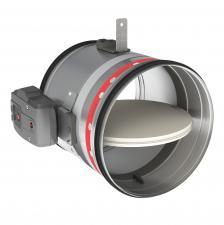
CR120+ONE T 24 • Motorized circular fire dampers EI120S
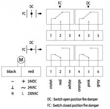
Circular fire dampers with a fire resistance of 120 minutes. When the temperature in the damper rises above 72 °C the thermo-electrical link will get triggered and the damper will close. When closed, the expanding material around the fireblade will swell and assure a fire and air-tight seal against hot air and smoke. The tunnel is made out of galvanized steel. The CR120 + ONE T 24 fire dampers have a automatic operating mechanism with actuator, with indication of the blade position. An end and begin of range switch is included within the actuator.
Application
- Fire compartimentation
- To close and seal off ventilation ducts in case of fire
- For air temperatures of -10°C up to temperature of the thermo-electric fuse
- For air with RV 0-96%
- Range of Ø100 up to Ø315 mm
- To be mounted horizontally or vertically
Material
- Galvanized steel
Construction
Composition
- Galvanized steel tunnel
- Fibersilicate fireproof blade
- Intumescent strip
- Actuator ONE T 24 FDCU with thermo-electrical fuse
- 1. Refractory casing (made out of galvanised steel)
- 2. Damper blade
- 3. Operating mechanism
- 4. Rubber sealing ring
- 5. Intumescent strip
- 6. Mounting plate thermo-electric fuse
- 7. Positioning plate
- 8. Sealing ring damper blade
- 9. Fusible link
- 10. Blade position indicator
- 11. Unlocking button
- 12. Battery compartment to reset motor (9V)
- 13. LED
Mounting
- To be inserted in fire resistant walls or floors and to be fixed according to the mounting instruction delivered with the valves.
- To be connected with round air ducts
- To be electrically wired to the fire detection system or building system
Certification
- Classified EI120(ve,ho i<->o)S at 500Pa according EN 13501-3 in ridid wall and rigid floor.
- Classified EI60(ve i<->o)S at 500Pa according EN 13501-3 in flexible wall.
- Certified with test report Efectis 09-A-087 / EFR-19-005412 or WFRG 16127B
- Airtight EN 1751 class C
- CE marked
Accessories
- Fire resistant plaster, type BP
Other available products
- For bigger sizes see CR2 + ONE T 24
Text for tender
- The fire dampers shall be of the round type with a fire resistance of 120 minutes, certified according to EN13501-3 . They will consist of a galvanized steel tunnel and fireproof fiber silicate valve. The control mechanism will be automatically operated by means of an actuator and shall have a blade position indicator and thermo-electrical link of 72 °C
- type CR120 + ONE T 24
Order example
- CR120 + ONE T 24, 160
Explanation
CR120 = Round fire damper with fire resistance of 120 minutes
ONE T 24 = Actuator 24V with thermo-electrical fuse
160 = Connection diameter
Informatie aanvragen. Even geduld a.u.b...


