PRODUCTS
EShop-number
Password
Welcome to CAIROX BELGIUM
CR60+MFUS • Circular fire dampers EI60S
 |
 |

- Fire dampers
- Circular
- EI60S
- With fuse 72°C
- EN1366-2
- Ø 100 - 315
Accessories
FDCU MFUS • Begin/end of range switch for MFUSCircular fire dampers with a fire resistance of 1 hours. When the temperature in the damper rises above 72 °C the fusible link will break and the damper will close. When closed, the expanding material around the fireblade will swell and assure a fire and air-tight seal against hot air and smoke. The tunnel is made out of galvanized steel. The CR60 + MFUS fire dampers have a manual operating mechanism with indication of the blade position. Optionally, an end and begin of range switch FDCU MFUS can be added to the mechanism. The operating mechanism can be removed easily, for inspection purposes or for replacing the fusible link.
Application
- Fire compartimentation
- To close and seal off ventilation ducts in case of fire
- For air temperatures of -10°C up to temperature of fusible link
- For air with RV 0-96%
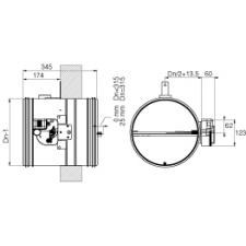
- Range of Ø100 up to Ø315 mm
- To be mounted horizontally or vertically
Material
- Galvanized steel
Construction
Composition
- Galvanized steel tunnel with rubber duct sealing
- Fibersilicate fireproof blade
- Intumescent strip
- Manual control mechanism MFUS with fusible link 72 °C
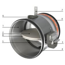
- 1. Refractory casing (made out of galvanised steel)
- 2. Damper blade
- 3. Operating mechanism
- 4. Rubber sealing ring
- 5. Intumescent strip
- 6. Mounting plate for thermo-electrical fuse (not used on manually controlled dampers)
- 7. Positioning plate
- 8. Sealing ring damper blade
Mounting
- To be inserted in fire resistant walls or floors and to be fixed according to the mounting instruction delivered with the valves.
- To be connected with round air ducts
Certification
- Classified EI90(ve,ho i<->o)S at 300Pa according EN 13501-3 in ridid wall and rigid floor.
- Classified EI60(ve i<->o)S at 500Pa according EN 13501-3 in flexible wall.
- Certified with test report Efectis 07-A-057 / EFR-19-005411 or WFRG 16126
- Airtight EN 1751 class C
- CE marked
Accessories
- Fire resistant plaster, type BP
- End- and begin of range switch, type FDCU MFUS
Other available products
- For bigger sizes see CR2 + CFTH
Text for tender
- The fire dampers shall be of the round type with a fire resistance of 60 minutes, certified according to EN13501-3 . They will consist of a galvanized steel tunnel and fireproof fiber silicate valve. The control mechanism will be manually operated and shall have a blade position indicator and fusible link of 72 °C
- type CR60 + MFUS
Order example
- CR60 + MFUS, 160
Explanation
CR60 = Round fire damper
MFUS = Mechanism
160 = Connection diameter
Requesting information. Please wait a moment...


