This site uses cookies and related technologies, as described in our privacy policy, for purposes that may include site operation, analytics, enhanced user experience, or advertising. You may choose to consent to our use of these technologies, or manage your own preferences.
White fire resistant ventilation exhaust valves with thermal fuse of 70°C and fire resistance class EI60(veo->i)S
Application
For ventilation purposes and fire compartimentation in walls with fire resistance of 60 minutes
Material
Steel
Colour
White, RAL 9010
Construction
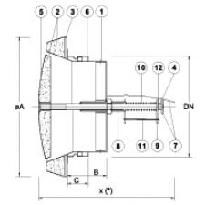
Composition
Steel body with white powder coated finish
Moulded fireproof heat-resistant material
Disc in ceramic felt
Threaded rod
Central core in powder coated steel
Standard mounting frame in galvanized steel
Locking device
Threaded support with fuse
Fuse-hook
Return spring in steel
Fuse 70°C
Locking clips
x: total length when locked (after exposure to heat)
Mounting
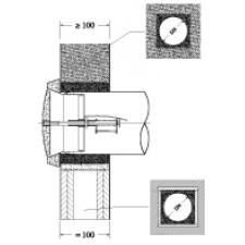
The valve should be mounted in a brick wall or partition gypsum plaster, according to the following methodology:
Make a reservation DN + 40 mm in the wall crossing. Ø particular case of a partition gypsum: spare a square booking dimension (DN 70) x (DN 70) therein a trimmer with a headband Promatect'H thickness 15mm.
Fix the pipe in DN standardized circular, to the mounting flange.
Position and the wedge together in the center of the book so that the folded edge of the flange comes into bare outer face of the receiving valve.
Grouting periphery coated with gypsum mixed with sand.
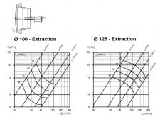
Adjusting the opening of the movable part of the valve (see graphs)
Install the valve set in the standby position, in its collar by rotating 1/4 turn: to build on the outer edge of the body: do not put stress on the central core!
Certification
CE Certified under the name BCF-2-EI60S
CE certified 1812-CPD-1039
Conforme according EN15650-2010
Classification EI60(veo->i)S
Service pressure 300Pa
Fuse tested according ISO 10294-4
Accessories
Mountingframe (included)
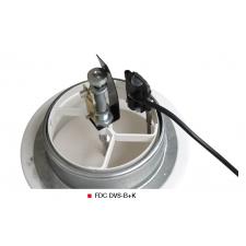
End of range switch, type FDC DVS-B+K
Text for tender
The ventilation valves will be fire resistant EI60(veo->i)S with thermal fuse of 70° and equipped with mountingframe.
Finished white, RAL 9010
type DVS-B+K
The ventilation valves will be fire resistant EI60(veo->i)S with thermal fuse of 70° and equipped with mountingframe.
Finished white, RAL 9010
type DVS-B+K
Order example
DVS-B + K, 125
Explanation
DVS-B+K = Type of fire resistant valve
125 = Connection diameter
Artikelen
Artikelselectie-assistent
Type
Grootte
Type
Oriëntatie
Spanning [V]
Artikelnummer
Type
Grootte
Type
Oriëntatie
Spanning [V]
E-shop
I050115125235
HF R EC 125-15D GR360
125
15D
GR360**
230
I050115125236
HF R EC 125-15D GL360
125
15D
GL360**
230
I050115125237
HF R EC 125-17D GR360
125
17D
GR360**
230
I050115125238
HF R EC 125-17D GL360
125
17D
GL360**
230
I050115125239
HF R EC 125-15D GR090
125
15D
GR090**
230
I050115125240
HF R EC 125-15D GL090
125
15D
GL090**
230
I050115125241
HF R EC 125-17D GR090
125
17D
GR090**
230
I050115125242
HF R EC 125-17D GL090
125
17D
GL090**
230
I050115140235
HF R EC 140-15D GR360
140
15D
GR360**
230
I050115140236
HF R EC 140-15D GL360
140
15D
GL360**
230
I050115140237
HF R EC 140-17D GR360
140
17D
GR360**
230
I050115140238
HF R EC 140-17D GL360
140
17D
GL360**
230
I050115140239
HF R EC 140-15D GR090
140
15D
GR090**
230
I050115140240
HF R EC 140-15D GL090
140
15D
GL090**
230
I050115140241
HF R EC 140-17D GR090
140
17D
GR090**
230
I050115140242
HF R EC 140-17D GL090
140
17D
GL090**
230
I050115160235
HF R EC 160-15D GR360
160
15D
GR360**
230
I050115160236
HF R EC 160-15D GL360
160
15D
GL360**
230
I050115160237
HF R EC 160-17D GR360
160
17D
GR360**
230
I050115160238
HF R EC 160-17D GL360
160
17D
GL360**
230
I050115160239
HF R EC 160-15D GR090
160
15D
GR090**
230
I050115160240
HF R EC 160-15D GL090
160
15D
GL090**
230
I050115160241
HF R EC 160-17D GR090
160
17D
GR090**
230
I050115160242
HF R EC 160-17D GL090
160
17D
GL090**
230
I050115180235
HF R EC 180-15D GR360
180
15D
GR360**
230
I050115180236
HF R EC 180-15D GL360
180
15D
GL360**
230
I050115180237
HF R EC 180-17D GR360
180
17D
GR360**
230
I050115180238
HF R EC 180-17D GL360
180
17D
GL360**
230
I050115180239
HF R EC 180-15D GR090
180
15D
GR090**
230
I050115180240
HF R EC 180-15D GL090
180
15D
GL090**
230
I050115180241
HF R EC 180-17D GR090
180
17D
GR090**
230
I050115180242
HF R EC 180-17D GL090
180
17D
GL090**
230
I050115200235
HF R EC 200-15D GR360
200
15D
GR360**
230
I050115200236
HF R EC 200-15D GL360
200
15D
GL360**
230
I050115200237
HF R EC 200-17D GR360
200
17D
GR360**
230
I050115200238
HF R EC 200-17D GL360
200
17D
GL360**
230
I050115200239
HF R EC 200-15D GR090
200
15D
GR090**
230
I050115200240
HF R EC 200-15D GL090
200
15D
GL090**
230
I050115200241
HF R EC 200-17D GR090
200
17D
GR090**
230
I050115200242
HF R EC 200-17D GL090
200
17D
GL090**
230
I050115250235
HF R EC 250-15D GR360
250
15D
GR360**
230
I050115250236
HF R EC 250-15D GL360
250
15D
GL360**
230
I050115250237
HF R EC 250-17D GR360
250
17D
GR360**
230
I050115250238
HF R EC 250-17D GL360
250
17D
GL360**
230
I050115250239
HF R EC 250-15D GR090
250
15D
GR090**
230
I050115250240
HF R EC 250-15D GL090
250
15D
GL090**
230
I050115250241
HF R EC 250-17D GR090
250
17D
GR090**
230
I050115250242
HF R EC 250-17D GL090
250
17D
GL090**
230
** Oriëntatie te bepalen aan de hand van onderstaande technische tekening
Quick selection
Q
DVS-B+K
100
125
s
3
6
9
12
3
6
9
12
30
Ps
40
12
Lw(A)
32
25
40
Ps
75
25
45
Lw(A)
40
25
27
60
Ps
50
18
100
30
Lw(A)
44
35
40
25
80
Ps
32
18
51
Lw(A)
43
36
34
100
Ps
50
28
80
35
Lw(A)
50
42
42
32
120
Ps
40
51
24
Lw(A)
48
39
32
140
Ps
70
30
Lw(A)
48
36
180
Ps
50
Lw(A)
45
Selection graphs
Symbols and specifications
Q = Air volume in m³/h
Ps = Static pressure in Pa
s = Distance between the central cone and the body of the valve in mm